
Marine engine oil cooler

Overview:
Two cores from a marine diesel motor oil cooler had been obtained for evaluation to research the reason for failure via leaking. Outcomes suggest your cooler core failed due to pitting corrosion started on inside (oil side) on edge of the fins. The orientation for the leaks was consistent with corrosion as a result of drop-out of condensed moisture or sludge in the bottom interior edges of this fins.
The cooler is made of 0.014-in. dense ferritic chromium stainless fins put together by copper brazing to a decreased carbon steel mounting plate. No manufacturing flaws were noted.
ANALYSIS:
Two cores from a marine engine oil cooler were obtained for evaluation. The cores had been identified for reasons of the report via letters “A” and “B”. Reportedly the coolers are from a twelve cylinder Detroit Diesel two-stroke marine engine. The motor was in service for eleven years. Apparently the operating time regarding engine is 770 hours.
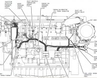
Figure 1 shows a side-view of oil cooler core “B” as gotten for evaluation. Both piles in the core are focused horizontally (as shown) whenever set up in the motor. Figure 2 reveals an oblique view of core “B”. There are 2 stacks of hollow air conditioning fins attached with a mounting dish. Each bunch on each core features an inlet and an outlet opening. Oil circulates in the fins although the coolant circulates outside. Stamped identification scars regarding the mounting dishes of both cores read:
 * **
* **
*********
**********
**********
← IN away →
The “9 94” recognition level probably suggests a manufacture time of September 1994 in line with the coolers becoming original gear for this motor.
Spectrographic chemical evaluation of the installation dishes was carried out according to ASTM E415-99a. Results indicate the plates are manufactured from reasonable carbon metallic with reasonable impurity levels, most likely for increased forming properties. Chemical evaluation answers are supplied in dining table 1. No strange conditions had been seen in the compositions.
The cores were leak tested by pressurizing with environment. Figure 3 provides a bottom view of one bunch (“B2”) of fins from oil cooler core “B”. Leak assessment unveiled the leak ended up being located in the boxed area, and stereomicroscope evaluation revealed several pinhole leakages at sides of fins. Core “A” didn't drip during evaluating.
Figure 4 reveals a close-up side-view of a typical pinhole drip location on bunch “B2”. The drip is located at a bottom advantage where the fin overlaps for a braze joint. One pinhole drip location on a fin was examined making use of a scanning electron microscope (SEM). The lowest magnification SEM overview of the drip, Figure 5, shows a roughly rectangular opening with irregular sides. Figure 6 is an increased magnification SEM view associated with reduced side of the hole that shows the steel features an exceptionally thin side consistent with deterioration. Figure 7 shows an increased magnification SEM view associated with upper side of the opening, which includes an irregular contour.
 The fin had been slashed available for study of the inner. Figure 8 is a close-up interior view of the pinhole drip. The drip website is a corrosion gap. Corrosion has exposed the edge of a brazed lap joint. A number of reinforcing ribs are also noted. Figure 9 is an oblique SEM interior view for the pinhole leak, which much more clearly shows both corrosion pit additionally the strengthening ribs. Figure 10 is yet another SEM interior view of the pinhole drip that reveals the oval form of the deterioration pit. Two boxed areas are shown at greater magnification in Figures 11 and 12. Figure 11 reveals the bottom of the pit into the fin and braze material in which etching from deterioration has uncovered the grain boundaries in both products. Figure 12 is a higher magnification SEM view of the outer edge of the pit, which reveals grain boundary facets with additional smaller pits. The intergranular gap morphology confirms corrosive assault while the pitting procedure.
The fin steel and braze material had been examined by energy dispersive spectroscopy (EDS) per ASTM E1508 at the locations suggested in Figure 11. Figure 13 presents an EDS spectral range of the fin product. Large iron peaks, and a smaller sized chromium top are detected along with small amount of manganese, silicon, and copper indicating the fin material is a chromium stainless. Figure 14 provides an EDS spectrum of the braze product. Huge copper peaks and smaller metal and chromium peaks tend to be detected, suggesting a copper based braze alloy was useful for assembly. No zinc or phosphorus were mentioned (these elements have a tendency to develop brittle substances in stainless steel braze bones).
A cross-section was taken through the pinhole leak an additional fin an additional comparison fin in identical pile during the area shown in Figure 3. The cross-section samples were ready for metallographic evaluation prior to ASTM E3-01. Etching in accordance with ASTM E407-99 unveiled the microstructures that have been examined utilizing an optical microscope prior to ASTM E883-02.
Figure 15 shows the lowest magnification optical microscope view of a cross-section through a comparison fin. Within the cross-section, the ends regarding the fin are J-shaped and overlap within brazed lap joint. Extra copper braze joints connect the metallic ribs into fins.
Figure 16 shows a reduced magnification view of a cross-section through among the pinhole leakages from the oil cooler core. Note the thinning for the stainless-steel due to inner pitting corrosion. The drip is revealed at increased magnification in Figure 17, which shows that pitting corrosion right beside the drip has actually thinned the fin to not as much as a tenth of their original width. Figure 18 shows the overlap location right beside the pinhole leak. Addititionally there is thinning of metal because inner pitting deterioration. The microstructure of the stainless steel fins is polygonal ferrite grains, that will be regular.


Share this article
Related Posts


Latest Posts


